Ion exchange capacity
Introduction
Ion exchange is a cyclic process: ions are loaded to resins, the resins get progressively exhausted, and when there is no place to load more ions, the loading phase is interrupted, and the resins must be regenerated.
Ion exchange capacity indicates the quantity of ions loaded to the resin.
Definitions
Total capacity
The total capacity of a resin sample is the number of ion exchange sites. See details at the end of the page. Typical capacity values are given below.In other words, the total capacity is the maximum theoretical quantity of ions that the resin can load.
Operating capacity
Also called useful capacity, it is the number of ion exchange sites where exchange has really taken place during the loading run. It is also the number of resin charges — not the number of ions because some ions have more than one charge — picked up by the resin in one cycle.In other words, the operating capacity is the actual quantity of ions loaded on the resin between regenerations. It depends on several parameters.
The ion exchange capacity is expressed as eq/L (equivalents per litre of resin).
The unit of mole should be avoided altogether in ion exchange, as it does not take valence into account and brings only confusion. For reference: 1 eq = 1 mole / valence.
The operating capacity is always smaller than the total capacity. We will see why.
Zone of exchange
Ideal case
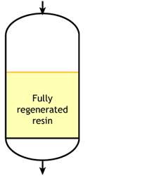 Start of the run |
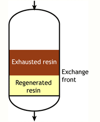 Middle of the run |
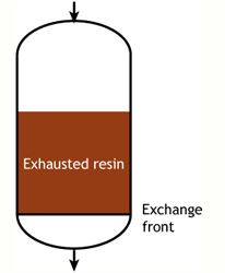 End of the run |
In an ideal case, we would start with a fully regenerated resin. During the exhaustion run, the exchange front would be absolutely flat, meaning that each infinitesimal resin layer would be instantaneously converted from regenerated to exhausted, capturing the incoming ions with an infinite speed of exchange. This flat front would move down the column as more ions are removed from water. At some point, the flat front would reach the bottom of the column, and the resin would then be totally exhausted. In such a case, the operating capacity would be equal to the total capacity of the resin. This case does not exist in practice, as the exchange front is not flat and the resin is not always fully regenerated at the beginning of the run.
In the real world, there are two cases:
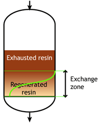
Case 1: the resin is totally regenerated at the beginning of the run (WAC & WBA)
 Start of the run |
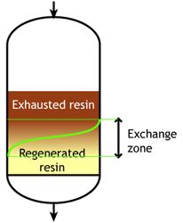 Middle of the run |
 End of the run |
At the start of the run, the resin is totally regenerated. In the course of the loading run, the top layers of the bed get progressively exhausted. However, the exchange reaction is not infinitely fast, as the ions must find their way to available sites inside each resin bead. Therefore, some ions find their way to lower levels of the bed before the layers above are totally exhausted. The area between fully regenerated and fully exhausted resin is called exchange zone or reaction zone, as shown in the pictures.
At some stage, the ions begin to "leak" iinto the treated water. The loading run is stopped at the time the concentration of this ion leakage reaches a preset value. This is called the endpoint of the run. At this stage, the ion exchange resin is not fully exhausted, so the operating capacity is smaller than the total capacity.
The operating capacity is, as defined above, the difference between the exhausted resin at the start and at the end of the run. The behaviour shown here is typical of weakly acidic and weakly basic ion exchange resins, that can be fully regenerated with a minimum amount of regenerant, close to the stoichiometric value. A stoichimetric regenerant quantity is the quantity of chemical equivalents exactly equal to the ionic load during the exchange cycle. In practice, weak resins are regenerated with a small excess over the stoichiometric quantity.
The typical operating capacity of a weak base anion exchange resin is 70 to 90 % of the total capacity. For weak acid cation resin, operating capacity depends on several parameters, so there is no such simple estimate. However, WAC resins having a high total capacity and being regenerated almost stoichiometrically, i.e. without an excess (see regenerant ratio), their use is very helpful for waters containing a high concentration of alkalinity and hardness.
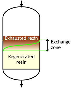
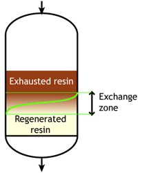
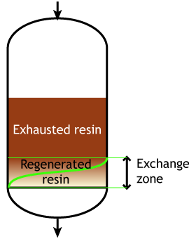
Case 2: the resin is partially exhausted at the beginning of the run (SAC & SBA)
 Start of the run |
 Middle of the run |
 End of the run |
This second case is typical of strongly acidic and strongly basic resins, which are more difficult to regenerate, so that an excess of regenerant chemical must be passed through the resin bed. Even so, it is not economical to regenerate the resin totally, which would mean a very high regenerant dosage, so in practice the resin bed is only partially regenerated. The pictures here indicate a resin bed with downflow loading and upflow regeneration. See the page about regeneration details.
Typically the operating capacity of SAC and SBA resins is 40 to 60 % of their total capacity.
Case 2b: co-flow regenerated resins
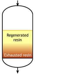 Start of the run |
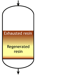 Middle of the run |
 End of the run |
The feed water during the exhaustion run and the regeneration solution are both flowing from top to bottom. As a result, the top layers of the resin bed are well regenerated at the start of the run, but the bottom of the bed is not. During the exhaustion run, a fraction of the ions from the feed not removed during regeneration leak into the treated water, as shown in the regeneration page.
For example, if the resin is regenerated with acid, some of the H+ ions released by the removal of Na+ ions from the feed wander down the column and displace a few of the Na+ ions left at the bottom after the previous regeneration. The sodium leakage is thus much higher than with reverse flow regeneration.
Ion exchange kinetics
Weak acid and weak base resins are sensitive to flow rate. When the flow rate increases, the reaction zone becomes longer.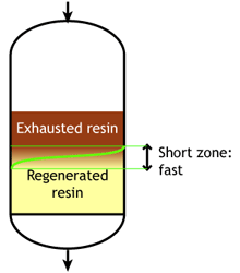 Low flow rate: the reaction zone is short |
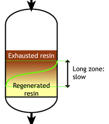 High flow rate: the reaction zone is long |
When the reaction zone is short, the achievable operating capacity is higher, because a higher fraction of the total capacity can be used before the leakage reaches its endpoint.
SAC and SBA resins are less sensitive to flow rate.
Fine resins have generally higher kinetics; this is especially true for WAC and WBA resins. The reason is a shorter path for the ions to travel inside the resin beads.
Parameters affecting operating capacity
 The operating capacity depends on a number of process variables including:
- Concentration and type of ions to be adsorbed
- Service flow rate
- Temperature
- Type, concentration and quantity of regenerant
- Type of regeneration process (co-flow, reverse flow...)
- Bed depth (reverse flow regeneration only)
- Particle size of the ion exchange resins
Measurement of the total capacity
The total capacity of a resin sample is measured by titration and expressed in eq/L. The procedure involves a volume measurement and must be carried out under strict conditions. As the volume changes according to the ionic form of the resin — some ions have a higher mass and their volume is different from others — the ionic form of measurement must always be reported.The total capacity must also be reported as dry weight capacity after drying of the resin sample. The dry weight capacity measures the number of active groups per kg of dry resin, i.e. without the moisture content. It is expressed in eq/kg. Mention of the ionic form is critical here as well, as different ions have different masses.
Dry weight capacity is important for two different purposes:
- For new resins, it gives information about the efficiency of the activation process: for instance, if every aromatic ring has been sulphonated in a strongly acidic resin, the theoretical maximum total dry weight capacity is about 5.5 eq/kg in H+ form.
- For used resins, it gives information about a possible fouling: a fouled resin sample contains foreign matter, which increases the dry weight, and as a consequence the dry weight capacity (number of active groups per kg of dry matter) decreases, even if no functional group has been lost.
Operating capacity in practice
We have seen that the operating capacity of an ion exchange resin is a fraction of the total capacity. It is also expressed in eq/L (equivalents per litre of resin) and indicates the quantity of ions (more precisely the number of charges) that can be exchanged during a cycle.The following table shows typical total and operating capacity values for the common resins (all values in eq/L, most common value in brackets):
| Resin type* | Total capacity | Operating capacity |
|---|---|---|
| WAC | 3.7 to 4.5 [4.2] | 1.0 to 3.5 |
| SAC | 1.7 to 2.2 [2.0] | 0.6 to 1.7 |
| WBA | 1.1 to 1.7 [1.3] | 0.8 to 1.3 |
| SBA | 0.9 to 1.4 [1.2] | 0.4 to 0.9 |
Let's consider for example a strongly acidic cation exchange resin (SAC) used for softening, and let's assume the water to be treated has a hardness concentration of 4.4 meq/L and the resin, under specific operating conditions, has an operating capacity of 1.1 eq/L, which is 1100 meq/L.
Each litre of ion exchange resin will thus be able to treat 1100 / 4.4 = 250 litres of the hard water before having to be regenerated. In ion exchange jargon, this means that the throughput is 250 bed volumes. If the water hardness is higher, the throughput will be less, and vice-versa. See also concentration and capacity units.
Experimental calculation of the operating capacity
Softening example
You have an ion exchange column containing a volume V (litres) of SAC(Na) resin. The water you are treating contains a concentration C of hardness expressed in meq/L. To measure and calculate the operating capacity, you must measure continuously the residual hardness coming out of the column, or take a sample every few minutes (say 5 to 15 min) and analyse its hardness. Plotting the individual residual hardness values should produce the following red curve.R = Q · C
And the operating capacity of your column is:
Cap = Q · C / V (meq/L)
Example: your column holds V = 2000 L of resin (Amberjet 1000 Na), your feed water contains C = 6 meq/L of hardness, your throughput Q is 360 m3 = 360'000 L, so the operating capacity of the column is
Cap = (360'000 · 6) / 2000 = 1080 meq/L = 1.08 eq/L
Exactly the same calculation would apply to a nitrate removal column using a nitrate-selective SBA resin, where the nitrate concentration would be used instead of hardness.
Performance profiles in demineralisation
The situation here is more complicated, because you have at least two resin types (cation and anion exchangers), and sometimes three or four (weak and strong). If you have two resins only, the cation resin profile is similar to the above graph, but you would use the conductivity (after the anion column) as a control parameter instead of hardness. To calculate the cation resin capacity, you would need the total cation concentration in the feed water, and for the anion resin you would need the anion concentration after degasifier (if any) making sure to add silica and free CO2 to the anions.WAC resin
- At the beginning of the run, the resin produces some free mineral acidity. It looks like if the weakly acidic resin had strongly acidic groups, although this is not the case. The leakage of free mineral acidity disappears after a while, and is replaced by an alkalinity leakage.
- This alkalinity leakage determines the endpoint of the run. In dealkalisation systems, the standard endpoint is reached when the alkalinity leakage is 10% of the alkalinity in the feed water. See also dealkalisation leakage profile with more details.
- In demineralisation, when the WAC resin is paired with a SAC resin, it is not necessary (and indeed not possible in case of Stratabed or multi-chamber Amberpack systems) to monitor the quality at the outlet of the WAC resin: only the sodium leakage at the outlet of the SAC resin is important (see next section).
SAC resin
- The pH value at the outlet of the SAC resin is low (2 to 4) as long as the resin has available capacity, i.e. when it produces H+ ions. When the resin approaches exhaustion, less H+ ions are produced, and the pH value increases.
- The profile of free mineral acidity is symmetrical to that of pH: during the service run, the resin produces free mineral acids; at the time of breakthrough, sodium salts appear in the effluent, i.e. FMA decreases.
- The conductivity value at the outlet of the SBA resin downstream (provided it has enough anion capacity) reflects the sodium leakage from the SAC resin: it remains low until sodium ions appear at the outlet of the cation column.
- If you want to check the real conductivity profile at the outlet of the cation column, a direct measurement is not helpful, as the water contains all anions (now as acids). Instead, you should prepare a small, laboratory-scale column of highly regenerated SBA resin (e.g. nuclear grade resin) and run a sample of the water from the outlet of the SAC unit through that column. The conductivity from the outlet of the lab column will give a good idea of the sodium leakage from the cation unit.
- There should be no measurable hardness at the outlet of a SAC resin column used in demineralisation. The presence of TH would indicate a serious problem of regeneration, or channeling in the resin bed, or precipitation of calcium sulphate if the resin is regenerated with sulphuric acid.
WBA resin
- The weakly basic resin picks up free mineral acids. Therefore, the pH value is relatively high at the beginning of the run. If the water is degassed (degasifier before WBA resin) the pH value is higher, otherwise the carbonic acid in the treated water brings it down a little.
- Conductivity usually lies between 5 and 20 µS/cm, somewhat higher in the presence of large quantities of CO2. When hydrochloric acid breaks through the conductivity increases again.
- In plants with a combination of WBA and SBA resins, it is not necessary to follow up the profile of the WBA resin. Actually the WBA resin is most often overrun, some of the free mineral acids finding their way to the SBA resin. This occurs always in Stratabed, Stratapack and multi-chamber Amberpack designs. The quality of the treated water is controlled at the outlet of the SBA resin (see next section).
SBA resin
- At the outlet of the SBA resin vessel, both silica leakage and conductivity must be monitored. If the cation resin has extra capacity, silica breakthrough will occur before conductivity breakthrough. This is not desirable, because silica is more difficult to monitor than conductivity. Therefore the anion resin should be calculated (at the time of design) with a larger safety factor.
- In the case shown here, it is assumed that there is extra cation capacity (the undersirable case). One can see on the graph that the conductivity drops a little at the time of silica breakthrough. This is due to the fact that the specific conductivity of sodium silicate is lower than that of sodium hydroxide.
- In this case, when the conductivity increases again, it means that we are past the silica breakthrough, i.e. large quantities of silica are present in the treated water.
- The desirable case is where cation breakthrough comes first.
- The pH value of the treated water is also plotted on the graph. It should be noted however that the measurement of pH is problematic in pure water. Therefore, pH should not be used as a primary process control. Abnormalities in pH values can however give some indications about which type of resin is susceptible to be the cause of an operational problem.
Important remark
The tests should not be done with "virgin" resins. A few cycles (typically two or three) must be performed before the system reaches an equilibrium. The capacity of the first run (called cycle zero) is higher than that obtained in the subsequent cycles, because in this first run the resin is totally regenerated, which is not the case later.Suggestions for a basic laboratory setup and operating conditions are shown here.


